HOME ASSISTANT: NORD POOL SPOT PRICES AND HOW TO AUTOMATE DEVICES FOR CHEAPEST HOURS

All credits to Creating Smart Home

Most of this information can already be found around the internet, but since I wanted to integrate one as well for my Home Assistant instance, why not to share the same with you?

Integrating Nord Pool to the Home Assistant

First we need to get the Nord Pool prices into the system so a new integration is needed. Luckily (again) someone has already made it happen and it can be installed using HACS. If you don’t know what HACS is, it’s a Home Assistant Community Store, a place where tons of integrations and frontend elements are published and can be easily installed. Just need to remember that those are not official Home Assistant components and are maintained by individual people and therefore can break more easily than official ones.

Anyway, start by installing Nord Pool custom component. This integration does not have UI configuration so the has to be done manually to the configurations.yaml.

For example, here’s my config:

Add the following code in the sensor segment. If you already have sensors defined, omit the "sensor:" line

sensor:
  - platform: nordpool
    VAT: true
    currency: "EUR"
    price_in_cents: true
    region: "FI" // check nordpool website for your region
    precision: 3
    price_type: kWh

In above configration firstly we enable the integration and second we configure the sensor to use region Finland and currency in Euros. Some tweaking to precision and VAT is also done, but more configuration details can be found from the integration repository.

After everything is configured, restart the Home Assistant and continue to the UI part.

Making the UI

First let’s find the entity id from our integrations. In Home Assistant go to Settings->Devices & Services->Entities and search with the filter ‘nordpool‘. You should find a entity id (that is same as unique id) and write it down somewhere. Unique id is generated by the Nord Pool integration from the configuration we made in the previous chapter.

For this part I’m using Apex Charts Card that is very versatile graphical presentation card of various values. Again, this frontend card can be installed using HACS. So go to the HACS and search for Apex and install it.

After installation is succeeded, it’s time to configure two cards (one for today and one for tomorrow).

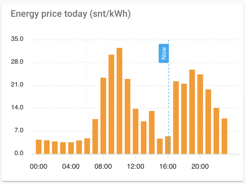
Here’s my configuration for the cards (example UI shown at the end of this chapter):

type: custom:apexcharts-card
graph_span: 24h
header:
  title: Energy price today (c/kWh)
  show: true
span:
  start: day
now:
  show: true
  label: Now
series:
  - entity: sensor.nordpool_kwh_fi_eur_3_10_024 // use your nordpool entity
    type: column
    data_generator: |
      return entity.attributes.raw_today.map((start, index) => {
        return [new Date(start["start"]).getTime(), entity.attributes.raw_today[index]["value"]];
      });
type: custom:apexcharts-card
graph_span: 1d
header:
  title: Energy price tomorrow (c/kWh)
  show: true
span:
  start: day
  offset: +1d
series:
  - entity: sensor.nordpool_kwh_fi_eur_3_10_024 // use your nordpool entity
    type: column
    data_generator: |
      return entity.attributes.raw_tomorrow.map((start, index) => {
        return [new Date(start["start"]).getTime(), entity.attributes.raw_tomorrow[index]["value"]];
      });

Again, you can use the same configurations, just remember to change the proper entity id for the cards (the one that we wrote down in previous chapter).

That’s it! Now there should be todays electrical spot prices and tomorrows spot prices available in the Home Assistant for any use!

To make it smart keep on reading the next chapters..

Finding the cheapest hours

One of the key points of having Nord pool is of course finding the cheapest hour(s) and automate devices to run during those hours.

For this I’ve created a template sensor that ensures validity of next day prices (usually published by Nord Pool at 12:00) and finds the sweet spot of requested lenght!

It’s easily modifiable by changing numberOfSequentialHours (how long period are we looking for), firstHour (first possible hour we want to start) and last hour (final hour we want to stop latest). E.g. you can also use it to find cheapest hours during the next night by setting the last hour to something like 06:00.

sensor:
  - platform: template
    sensors:
      cheapest_hours_energy_tomorrow:
        device_class: timestamp
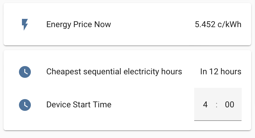
        friendly_name: Cheapest sequential electricity hours
        value_template: >
          {%- set numberOfSequentialHours = 3 -%}
          {%- set lastHour = 23 -%}
          {%- set firstHour = 0 -%}

          {%- if state_attr('sensor.nordpool_kwh_fi_eur_3_10_024', 'tomorrow_valid') == true -%}
            {%- set ns = namespace(counter=0, list=[], cheapestHour=today_at("00:00") + timedelta( hours = (24)), cheapestPrice=999.00) -%}
            {%- for i in range(firstHour + numberOfSequentialHours, lastHour+1) -%}
              {%- set ns.counter = 0.0 -%}
              {%- for j in range(i-numberOfSequentialHours, i) -%}
                {%- set ns.counter = ns.counter + state_attr('sensor.nordpool_kwh_fi_eur_3_10_024', 'tomorrow')[j] -%}
              {%- endfor -%}
              {%- set ns.list = ns.list + [ns.counter] -%}
              {%- if ns.counter < ns.cheapestPrice -%}
                {%- set ns.cheapestPrice = ns.counter -%}
                {%- set ns.cheapestHour = today_at("00:00") + timedelta( hours = (24 + i - numberOfSequentialHours)) -%}
              {%- endif -%}
            {%- endfor -%}
            {{ ns.cheapestHour }}
            {%- set ns.cheapestPrice = ns.cheapestPrice / numberOfSequentialHours -%}
          {%- endif -%}

Finally making the automations

Now that we know the cheapest hours for the next day, only thing to do is actually do the automations for various devices.

My automation is actually in two parts:

  • Second I run the automation when the time trigger is hit
# Helper to keep the start time
input_datetime:
  device_start_time:
    name: Device Start Time
    has_time: true
    has_date: false

automation:
# Update time trigger to cheapest hours
  - id: '1663398489357'
    alias: 'Set device start time'
    description: ''
    trigger:
    - platform: time
      at: '23:10:00'
    condition:
    - condition: not
      conditions:
      - condition: state
        entity_id: sensor.cheapest_hours_energy_tomorrow
        state: unknown
    action:
    - service: input_datetime.set_datetime
      data:
        time: '{{ as_timestamp(states(''sensor.cheapest_hours_energy_tomorrow'')) | timestamp_custom(''%H:%M'') }}'
      target:
        entity_id: input_datetime.device_start_time
    mode: single

# Finally do the actions when time trigger is hit
  - id: '1663399614818'
    alias: Increase heating
    description: ''
    trigger:
    - platform: time
      at: input_datetime.device_start_time
    condition: []
    action:
    - service: climate.set_temperature
      data:
        temperature: 24
      target:
        entity_id: climate.heat_pump
    mode: single

Setting up a WireGuard VPN server on the Raspberry Pi

Credits:
I Found this good tutorial for installing Wireguard on https://pimylifeup.com/raspberry-pi-wireguard/

In this section, we will do some initial preparatory work to make sure our Raspberry Pi is ready to install the WireGuard VPN software.

1. The first thing we need to do is ensure our Raspberry Pi is using the latest available packages.

We can do that by running the following two commands.

sudo apt update
sudo apt full-upgrade

2. We need to install the only package that we require to run the install scripts we need.

While this package should be available on most distributions of the Raspbian operating system, we will make sure by running the command below.

sudo apt install curl -y

Installing WireGuard on the Raspberry Pi

Within this section, we are going to make use of the PiVPN script to install WireGuard.

PiVPN makes the process of installing WireGuard on our Raspberry Pi a straightforward process. The script sets up the best defaults for our device.

Starting the PiVPN Install Script

1. Let us start the installation process by running the following command.

curl -L https://install.pivpn.io | bash

This command will use curl to download the PiVPN setup script from their website and then pipe it straight to bash.

You can verify this script’s contents by going directly to the install PiVPN domain in your web browser.

Installing WireGuard to your Raspberry Pi

1. The first screen you will be greeted with will let you know what this script is about to do.

To start the WireGuard installation process, press the ENTER key.

2. The first thing that we will be configuring through this script is a static IP address.

This screen explains why your Raspberry Pi should have a static IP address when operating as a WireGuard VPN server.

To proceed, press the ENTER key to proceed.

3. You will be asked if you are already using DHCP reservation.

Using DHCP reservation allows you to make your router assign an IP address to your Raspberry Pi.

In this guide, we are going to assume you haven’t used DHCP reservation and will move on to set a static IP address on  the Pi itself.

Select the <No> option and press the ENTER key to continue.

4. To set a static IP address for the WireGuard software. The installation script will want to use your default settings.

If the default IP address and gateway are correct to you, then you can safely select the <Yes> option.

Continue with this WireGuard set up guide by pressing the ENTER key.

5. You will be warned that you can potentially run into IP conflicts when using this method.

The way around that is to use DHCP reservation. However, most routers should be smart enough to stop this from being a problem.

Press the ENTER key to continue.

6. This screen will tell you that you need to specify a local user to store the WireGuard configuration files.

Continue to the next screen by pressing the ENTER key.

7. You can now select from a list of available users.

Use the ARROW keys to highlight the user then the SPACEBAR to select it.

Once you are happy with the user you have selected, press the ENTER key.

8. Finally, we can select the VPN software we want to install.

As we want to install WireGuard to our Raspberry Pi, you can press the ENTER key to continue.

The reason for this is that default by the PiVPN script selects WireGuard.

9. This screen will allow you to change the port the WireGuard uses on your Raspberry Pi.

It is recommended to keep this the same unless you have a particular reason to change the port.

Press the ENTER key to confirm the specified port.

10. This screen just confirms the port that you set your Raspberry Pi WireGuard VPN to use.

Please note to be able to access your WireGuard VPN from outside of your home network, you will need to port forward the port mentioned here. The type of this port is UDP.

Confirm that the port is still correct, then press the ENTER key to proceed.

11. We can now specify the DNS provider that we want to use for our VPN clients.

For our tutorial, we chose to use the Cloudflare one as it is relatively speedy, and they purge their logs every 24 hours.

Use the ARROW keys to navigate through this menu. Once you have found the DNS provider you want to use, press the SPACEBAR key.

If you are happy with your selection, press the ENTER key to confirm it.

12. You can specify two different ways you want to access your WireGuard VPN.

Using your public IP address is the easiest option. However, this should only be used if you have a static IP address.

The other option is to use a domain name. You can set up this option by following our dynamic DNS guide.

For this guide, we will be sticking with using our public IP address.

Once you have the option you want to be selected, press the ENTER key to proceed.

13. The PiVPN script will now generate the server key that WireGuard requires.

All you need to do here is press the ENTER key again.

14. This screen will give you a quick rundown about unattended-upgrades and why you should enable them.

Go to the next step by pressing the ENTER key.

15. You can now enable the unattended-upgrades by selecting the <Yes> option.

We highly recommend that you enable these to ensure your Raspberry Pi will download security fixes regulary.

Not enabling this will potentially leave your WireGuard VPN vulnerable to attack.

Once you have the option you want to be selected, press the ENTER key to confirm it.

16. You have now successfully installed the WireGuard VPN software to your Raspberry Pi.

This screen will let you know that you still need to create profiles for the users, which we will cover in the next section.

Press the ENTER key to continue to the last two steps.

17. You will be asked whether you want to restart your Raspberry Pi before continuing.

We recommend that you choose the <Yes> option.

Once you have selected to reboot, press the ENTER key twice to restart.

Creating your First WireGuard Profile on your Raspberry Pi

Now that we have successfully installed the WireGuard software to our Raspberry Pi, we can create a profile for it.

To be able to create this profile, we will be making use of the PiVPN script again.

1. To begin creating a new profile for WireGuard, we need to run the following command.

sudo pivpn add

2. All you need to do is type in a name for the profile that you are creating.

For example, we will be calling our profile “PiMyLifeUp“.

Once you have created a profile, it will be stored within the directory specified in the output.

If you followed the previous steps and used the pi user, you will be able to find the config file within the /home/pi/configs directory.

As a final step edit the PiMyLifeUp in /home/pi/configs to include the listenport in the interface section, otherwise you will look like connected to the server, but no data is send.

[Interface]
PrivateKey = xxxxxxxxxxxxxxxxxx
Address = xx.xx.xx.xx/24
DNS = 9.9.9.9, 149.112.112.112
ListenPort = 51820

You can use the config file within here to set up your WireGuard clients. However, there is another method which we will go into in the next section.

Generating a QR Code for your WireGuard Profile

In this section, we will show you how to generate a QR code for the WireGuard profile we generated on our Raspberry Pi.

You will be able to scan this QR code using your device. This saves you from having to copy the config file from your device.

Luckily for us, the PiVPN software comes with a QR code generator that we can use.

1. To generate a QR code for your profile, you will need to start by running the following command.

Make sure you replace “PROFILENAME” with the name you set in the previous section. In our case, this will be “PiMyLifeUp“.

pivpn -qr PROFILENAME
or
pivpn -qr

And select the profile you are generating the QR code for

2. You can then scan this QR code using your iOS or Android devices.

You can find the WireGuard app on both the Google Play Store and the Apple App Store.

When scanning the QR code, you will be asked to enter a name for the profile.

At this point, you should now have successfully got a WireGuard VPN running on the Raspberry Pi.

Finally, when you have done all steps and are able to connect to the WireGuard server on your Pi, but unable to connect to your LAN or the internet, then run the following command and make the necessary repairs to get it fixed

pivpn -d

If you need to show the QR code for a profile afterwards, then use the following command

sudo su
qrencode -t ansiutf8 < /etc/wireguard/clients/PROFILE.conf

When you have imported the profile in your mobile app and did not change the profile.conf file manually, then change the listen port for the server in the wireguard app from automatic to 51820 or the port you used when installing the wireguard server.

You can use the following code to check the connection status of your clients

sudo wg show

This will be the displayed result

interface: wg0
public key: xxxxxxxxxxxxxxx=
private key: (hidden)
listening port: 51820

peer: xxxxxxxxxxxxxxxx=
preshared key: (hidden)
endpoint: xx.xx.xx.xx:xx
allowed ips: xx.xx.xx.xx/32
latest handshake: 24 minutes, 30 seconds ago
transfer: 99.52 KiB received, 314.70 KiB sent

Setting up a secure IoT network using UniFi

This tutorial goes over how to set up a secure internet of things (IoT) network in UniFi with Google Cast and Airplay across VLANs.

Objectives

  • IoT network segregated from main LAN
  • Allow routing between IoT network and main LAN for AirPlay and Google Cast, but no other traffic should be routed
  • Create a VLAN in the UniFi SDN which allows us to assign access ports to the IoT network for wired devices


1. Setup IoT LAN

First, we have to setup our network for the IoT devices. To do this, navigate to Settings > Networks > Create New Network in UniFi.

The network should be marked as Corportate and have a unique (unused) VLAN assigned to it. Follow your standard IP addressing scheme and assign a subnet. For home deployments, a /24 should have more than enough IP addresses for your devices.


2. Make the IoT WiFi Network

The majority of your Internet of Things devices will probably be connected using WiFi, so we have create a wireless network next. Navigate to Settings > Wireless Networks > Create Wireless Network in UniFi.

Next, expand the Advanced Options and tag this network with the same VLAN that we created earlier. In this case, it will be VLAN 6. You should also check the box near “Prevent this SSID from being broadcast” since this network doesn’t need to be publicly visible.


3. Secure the IoT Network – Routing & Firewall Rules

By now, you will have both an IoT VLAN and an IoT WiFi network. However, these are in no way segregated from your main LAN, and aren’t secure. Now, we will secure our IoT network.

3a. Allow Established/Related connections

The first rule we are adding is to allow established and related connections. If you aren’t sure what those are, you might want to check out this Wikipedia page.

To add this rule, go to Settings > Routing & Firewall > Firewall > Rules IPv4 > LAN In > Create New Rule in UniFi. Call it “Allow Established/related sessions” and make sure that it is run before the predefined rules. Make sure to select the Action as “Accept”. On the same page, under Advanced > States, check “Established” and “Related”. For “Source”, you want to select the “Network” option and select your Internet of Things VLAN in the dropdown. For “Destination”, again, select “Network”, and select your main LAN in the dropdown.

3b. Drop IoT to Main LAN

If you were to login to the IoT WiFi network right now and ping a device on your main LAN right now, it would respond. Now, we have to instruct the USG to disallow routing all traffic that does not match the rule we have just defined in the previous step.

Staying in the LAN In section, create another new rule. Name it “Drop IoT to Main”, and have it run After Predefined Rules. Ensure the action matches “Drop”, and select the Source to be from network “Internet of Things”, and the destination to be from network “LAN”.

4. Enable mDNS Reflector for Google Cast and AirPlay

Casting protocols like Google Cast and AirPlay use an IP routing concept called multicast to discover devices on the network and advertise themselves as players. Right now, our network would work as a walled-off network, but we would not be able to use Google Cast without switching our own device to the IoT network, which is not ideal and defeats the purpose.

Go to Settings > Services > mDNS and enable it, and Apply your settings changes.

Conclusion

You should now have a functioning and secure IoT network. If you connect to the IoT network, you shouldn’t be able to ping a device on the main LAN or reach it on the local area network. However, if you have something like a Google Home and you are on the main LAN, you should be able to cast to it despite it being on the secured IoT network.

Add Smartwares CIP-37210AT IP camera in Surveillance Station

I managed to add the Smartwares CIP-37210ET IP camera, which I got from the Action store, in Synology Surveillance Station. I will explain how I did it below.

First install your camera with the HomeWizard Cameras app from smartwares.eu.
Write down the camera password you created at the end of the wizard.

Next thing to do is assign a fixed IP address to the camera. The software of the camera doesn’t support that, so you need to do that in your internet router.

Once you have done that, open Surveillance Station and add a camera and choose quick installation

Then choose in the brand selection screen the option defined by user

In the path you need to enter the url for the stream using the camera password you created during the wizard in the app on your phone

rtsp://admin:PASSWORD@IP:554/live/av0?

PASSWORD: password you created
IP: the fixed IP you assigned to your camera

The link you have to enter is the above text except for the rtsp://

admin:abcde12345@192.168.0.240:554/live/av0?

Now you can test the connection and if everything is done right, you should see the video stream.

Synology Surveillance Station Home Mode Automation with Home Assistant

I have found a guide on the www, but it was not that 100% clear and I had to google a lot of things to be clear. But I got it 100% functional and will publish an updated guide here.

This is the url for the original guide: https://www.paolotagliaferri.com/home-automation-home-assistant-docker-synology/

Some prerequisites:

  • Docker
  • Home Assistant
  • Surveillance Station
  • Unifi network or similar that can be integrated in Home assistant

First:

Find the entity identifier of your mobile phone that is used by the Ubiquiti UniFi integration

Create a group where the entity that represents you in your configuration.yaml

Next:

Then on the Synology Surveillance Station, I generated two actions in the Action Rule section to create webhooks that Home Assistant can use for switching the Home mode on or off

First I will create the rule to enable home mode

Here you see the webhook url we will use in the secrets.yaml later on

Now you have create the rule to enable the Home mode in surveillance station. Next will be the disable Home mode rule

Here you see the webhook url we will use in the secrets.yaml later on

When you have followed all steps, this will be the result

Now we are going to define 2 variables for the webhooks in the secrets.yaml file. These variables will be used in the configuration.yaml later.

When that is done, we can go back to the configurations.yaml to define the webhooks so they can be used for automation

Finally – I defined the automation in the UI (or in the configurations.yaml file) – here’s the generated configuration

Last thing to do is to check the configuration for errors and if that passes, you can restart the Home Assistant server.

Now the moment you go out of range of your wifi, Synology Surveillance station will go out of home mode and vica versa. Keep in mind that the standard delay the Ubiquiti UniFi integration uses for switching from home to not home is 300 seconds.

Why You Should Change the WordPress Administrator User ID

If your WordPress blog or site is a victim of a targeted attack a malicious hacker can easily identify the WordPress administrator username manually or by using automated tools. If a malicious hacker identifies the username of your WordPress administrator, he can launch a brute force or dictionary attack specifically against the WordPress administrator account, thus making the attack an easier feat.

If the malicious attacker does not know the WordPress administrator username, he has to guess both the username and password during a brute force attack. This means that the chances that the attack will succeed are much less and the attack will take much longer to complete, and the longer the attack takes, the more the chances of you or the hosting provider identifying the attack, which is exactly what you want.

How to Manually Identify the WordPress Administrator Username

By default the ID of the built-in WordPress administrator account is 1. Therefore unless you change the ID of the WordPress administrator to a higher random number, anyone can use the URL below to identify the WordPress administrator username

https://www.wpwhitesecurity.com/?author=1

If the WordPress administrator ID is still set to 1 the user will be redirected to the below URL, where the new username is shown at the end of the URL. For example in the below URL, the username is superadmin.

https://www.wpwhitesecurity.com/author/superadmin/

How to Change the ID of the WordPress Administrator

Before you change the WordPress administrator account ID also ensure that the administrator account does not have any posts or pages assigned to it. If it does, change the author of such posts or pages to a user with Author role manually or write an SQL query to change the author ID of such posts automatically.

Once you have done a WordPress database backup, connect to your WordPress database using the MySQL command line tool or the web based phpMyAdmin and execute the below queries on the WordPress database:

UPDATE wp_users SET ID = 1024 WHERE ID = 1;

The above MySQL query will change the default WordPress administrator user ID from 1 to 1024 in the wp_users table, i.e. where the user credentials are stored.

UPDATE wp_usermeta SET user_id = 1024 WHERE user_id = 1;

The above MySQL query will change the default WordPress administrator user ID from 1 to 1024 in the wp_usermeta table, where user related data is stored.

Change Author ID / Attribution On All Posts In a Single Pass

To change the ID for all posts from the old ID to the new ID 1024. Type the following MySQL command:

UPDATE wp_posts SET post_author = 1024 WHERE post_author = 1;

Avoid WordPress User ID Conflicts

By default WordPress uses incremental values to assign user IDs to newly generated user accounts. Therefore while the built-in administrator will have a user ID of 1, the first user you create will have user ID 2, second user will have user ID 3 and so on. If you think you will create more WordPress users than the number you have used for your new WordPress administrator user ID, you should set the WordPress User ID auto increment value (the counter that WordPress uses to assign new accounts a unique ID) to a bigger value than the one used for the WordPress administrator account. To do so use the below query:

ALTER TABLE wp_users AUTO_INCREMENT = 2048

Once you execute the above query, WordPress will assign a user ID of 2049 to the next WordPress user you create.

MotionEye on Debian 10

Requirements

  • a machine running a recent Linux distro
  • python 2.7
  • tornado 3.1+
  • jinja2
  • PIL or pillow
  • curl, libcurl & pycurl
  • motion (optional)
  • ffmpeg (optional)
  • v4l-utils (optional)

The Motion Daemon

The motion daemon itself is optional, but needed in most cases. Install it (along with ffmpeg and v4l-utils) unless you configure a machine that will only act as a hub for other motionEye-based cameras.

Install Instructions

motionEye releases are uploaded to PyPI, so you can use the pip (or pip2) command to install it as well as (some of) its dependencies. Following are detailed instructions for some common distributions.

note 1: The given commands normally need to be run as root; type them in a root shell or use sudo before each command.

note 2: On systems where Python3 is the default Python interpreter, you should use the pip2command instead of pip.

note 3: If you are configuring a motionEye system that will only act as a hub for other motionEye-based cameras (i.e. no locally connected cameras and no IP cameras), you can skip installing motionffmpeg and v4l-utils.

note 4 : All commands require root; use sudo before each command or become root using su.

Installation:

  1. Install motionffmpeg and v4l-utils:
    • apt-get install motion ffmpeg v4l-utils
  2. Install the dependencies from the repositories:
    • apt-get install python-pip python-dev python-setuptools curl libssl-dev libcurl4-openssl-dev libjpeg-dev libz-de

      note: Python 2.7 is required. If your system still runs Python 2.6 or older, please upgrade.
  3. Install motioneye, which will automatically pull Python dependencies (tornadojinja2pillow and pycurl):
    • pip install motioneye

      note: If pillow installation fails, you can try installing it from official repos using apt-get install python-pillow.
  4. Prepare the configuration directory:
    • mkdir -p /etc/motioneye
    • cp /usr/local/share/motioneye/extra/motioneye.conf.sample /etc/motioneye/motioneye.conf
  5. Prepare the media directory:
    • mkdir -p /var/lib/motioneye
  6. Add an init script, configure it to run at startup and start the motionEye server:
    • cp /usr/local/share/motioneye/extra/motioneye.systemd-unit-local /etc/systemd/system/motioneye.service
    • systemctl daemon-reload
    • systemctl enable motioneye
    • systemctl start motioned
  7. To upgrade to the newest version of motioneye, after it has been released, just issue:
    • pip install motioneye –upgrade

      note that will update all the other required dependecies
    • systemctl restart motioneye

Accessing The Frontend

After having successfully followed the installation instructions, the motionEye server should be running on your system and listening on port 8765. Fire up your favorite web browser and visit the following URL (replacing [your_ip] with… well, your system’s IP address):

http://[your_ip]:8765/

Use admin with empty password when prompted for credentials.

Upgrading

Upgrading should be as easy as running the following command (as root):

  • pip install –upgrade motioneye

Enable network storage

Change the smb_shares in the motioneye.conf file from false to true

  • nano /etc/motioneye/motioneye.conf

Add Push Notifications to MotionEyeOS

MotionEyeOS is perfect for using your Pi as a CCTV camera. Want to detect movements while you’re out? Then read on…

One benefit of MotionEyeOS is its ability to detect motion and capture images and movies of what triggered it. You can also access a live stream of your camera online, even when you’re not home, which is handy if you want to check in every now and then. When away from home, being notified of any movement is very useful, and MotionEyeOS has a nifty option for custom notifications.

The full article can be found in The MagPi 43 and was written by Wesley Archer

This guide will assume you have already set up and configured MotionEyeOS. A Pushover licence is required, which costs £3.99/$4.99. For help, check out the MotionEyeOS wiki.

You’ll need

MotionEyeOS

Raspberry Pi

Pushover app for iOS or Android with full licence (£3.99/$4.99)

STEP-01 Create an application in Pushover

Pushover has a great, easy to use API. Before we start, we need to register an application with it. Click on Register Application under the Your Applications heading on the Pushover website (pushover.net). Give your app a name – something like RaspiMotion – and then make sure the type is Application. Give your app a quick description (e.g. ‘Push notifications sent by my Raspberry Pi’) and, if feeling creative, upload a custom icon which will show in your Pushover client app whenever a notification is sent.

STEP-02 Get your API token and user key

Once you have created your application, you should have access to an API token/key. This is a unique combination of numbers and letters – please keep this a secret! You’ll also need your user key, which is shown once you log into Pushover’s website. Okay, so you have an app and your API and user keys. You’ll now need to download (or recreate if you so wish) a simple Python script to tell your Raspberry Pi to work its magic once the script is called upon by MotionEyeOS.

STEP-03 Create your Python script

MotionEyeOS is not like Raspbian. You cannot use certain commands as you would normally, such as git clone, so we’ll have to create our Python script manually; you can also drag and drop using WinSCP if preferred. We also don’t need to use sudo, as we’re already logged in as root by default. Our script needs to live in the data folder, so let’s go there and create pushover.py using nano: cd /data nano pushover.py

cd /data
nano pushover.py

Once here, you’ll need to copy and paste or type in the code listing, while also including your API token and user key where required.

import httplib, urllib

conn = httplib.HTTPSConnection(“api.pushover.net:443”)
conn.request(“POST”, “/1/messages.json”,
urllib.urlencode({
“token”: “APP_TOKEN”, # Insert app token here
“user”: “USER_TOKEN”, # Insert user token here
“html”: “1”, # 1 for HTML, 0 to disable
“title”: “Motion Detected!”, # Title of the message
“message”: “Front Door camera!”, # Content of the message
“url”: “http://IP.ADD.RE.SS”, # Link to be included in message
“url_title”: “View live stream”, # Text for the link
“sound”: “siren”, # Define the sound played
}), { “Content-type”: “application/x-www-form-urlencoded” })
conn.getresponse()

STEP-04 Make your script executable

As with any script, we need to make sure it can be executed, otherwise it’s nothing more than a fancy collection of text! You can do this either from the command line or from within WinSCP. From the command line, make sure you’re in the data folder and then type: chmod +x pushover.py

chmod +x pushover.py

Or, if using WinSCP, select the pushover.py file in the data folder, then press F9. In the window that appears, change the permissions to 0755 and then click ‘OK’ to confirm.

STEP-05 Configure MotionEyeOS to use your script

Now that we have our script, we need to tell MotionEyeOS to use it when it detects motion. To do this, log in, go to the Motion Notifications menu and turn on the ‘Run A Command’ option. You then need to specify which command to run, which will be the Python script you just created – this is /data/pushover.py. Click Apply once done, to confirm the changes.

STEP-06 Test it out!

Hopefully, by now you have created your Python script, made it executable, told MotionEyeOS to use your script when it detects motion, and have the Pushover app installed on your smartphone or tablet. We now need to test that it works! Wave your hand in front of your camera (or you can do a dance if you’re feeling energetic!) and then shortly afterwards you should receive a notification via Pushover, warning you that motion has been detected!

Feel free to experiment with the script to customise the message displayed and sound played in Pushover.

MotionEyeOS on Raspberry Pi – Surveillance Camera System

Do you want to turn your Raspberry Pi into a surveillance camera system? The best way to do it is using MotionEyeOS. In this post we’ll show you how to get started with MotionEyeOS on your Raspberry Pi.

What is MotionEyeOS?

MotionEyeOS is a Linux distribution that turns your single-board computer into a video serveillance system. The MotionEyeOS supports the following devices:

  • Raspberry Pi (all versions);
  • Banana Pi;
  • Odroid C1/C1+, Odroid C2, Odroid XU4;
  • Pine A64/A64+.

MotionEyeOS Features

MotionEyeOS is the perfect solution to build your own surveillance system because it is simple to install and has a web-based, user-friendly interface that is responsive in practically any browser.

It supports most USB cameras, Raspberry Pi camera modules, and IP cameras. Additionally, it brings other useful features when it comes to a surveillance system:

  • Motion detection with email notifications
  • You can set set a working schedule
  • Take still images
  • Store your files in SD card, USB drive, or upload your files to Google Drive or Dropbox
  • Access your media files through FTP server or SFTP server

Parts Required

For this project we’re using the following parts:

  • Raspberry Pi 3 – read Best Raspberry Pi starter kits
  • Camera – Raspberry Pi camera V2 module, USB webcam or IP camera
  • Power Supply 
  • MicroSD Card

Installing MotionEyeOS

To install MotionEyeOs in your Raspberry Pi 3, follow the next steps.

Formatting your microSD card

You’ll install MotionEyeOS on a microSD card and then, insert the microSD card into your Raspberry Pi board. But first, you need to format you microSD card – there are several ways to do this, but we recommend following the next procedure:

  • Go to https://www.sdcard.org/downloads/formatter/ and download the SD Card Formatter software for your operating system.
  • Install the SD Card Formatter software.
  • With your microSD card connected to your computer, open the SD card Formatter application, and format your microSD card with the “overwrite format” option.

Downloading the OS Image

Choose the right image for your device: MotionEyeOS releases page. If you’re using the Raspberry Pi 3, choose motioneyeos-raspberrypi3-xxxxxxxx.img.gz.

Writing the Image

Next, extract the image from the .zip folder. Then, you can use win32diskimager or Etcher, to write the image onto the SD card.

We’re going to use Etcher. If you don’t have Etcher installed, you can click here and install it on your computer.

With the microSD card formatted, and connected to your computer, open Etcher. Select the image you’ve get previously, select your microSD card, and click Flash!

Booting MotionEye on Raspberry Pi

Follow the next steps to boot MotionEyeOS for the first time on your Raspberry Pi.

  • Insert the microSD card in the Raspberry Pi;
  • Connect an Ethernet cable – this is needed on the first boot;
  • Connect a camera. If you’re using the Raspberry Pi camera V2 module, make sure you’ve connected the camera in the right orientation as shown in the following image;
  • Apply power to your Pi, and wait for about 2 minutes for the system to be ready.

Now, to access your Raspberry Pi, you need to find your Pi’s IP Address

Finding Your Raspberry Pi IP Address

To Find your Raspberry Pi IP address, you can use Angry IP Scanner. The IP you’re looking for is the one with “meye” on the name, as shown in the following figure.

Accessing MotionEye For the First Time

Open your browser and type the Raspberry Pi IP address. You’ll see the MotionEye login page.

At the first boot, use the following credentials:

  • Username: admin
  • Password: [No password, leave blank]

If you have a camera connected to your Pi, it should be detected automatically, and you should see a live image from the camera. If you have an IP camera, you need to add it as network camera with the camera stream address with your login credentials for that camera

Foscam C1:

MJPEG – http://[IPADDRESS]:[PORT]/cgi-bin/CGIProxy.fcgi?cmd=snapPicture2&usr=[USERNAME]&pwd=[PASSWORD]

RTSP – http://[IPADDRESS]/videoMain

Initial Setup

You can configure pretty much everything in your web user interface. We recommend taking a look at the following configurations when configuring the MotionEyeOS for the first time.

  • Go to the three bars menu, and open the General Settings;
  • Enable Advanced Settings;
  • You can change the admin username and set a password;
  • You can also set a name for a surveillance user, and its corresponding password;
  • Set your timezone and a hostname.

Click the orange button at the top right “Apply” to apply the changes – this will require a reboot.

Wrapping Up

This was just an introduction on how to get started with MotionEyeOS on the Raspberry Pi 3. In this example we’re using a single device (the Raspberry Pi board) with two cameras, but it can be more useful using a Raspberry Pi 3 as a Hub, and then use several cameras in different locations

If you want to add push notifications in motionEye, then follow the next guide: https://www.tommybaert.be/add-push-notifications-to-motioneyeos/