Proxmox – Increase LV disk size

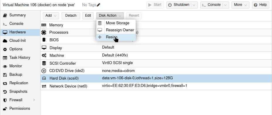
First increase your disk size in the GUI of proxmox

Then open the terminal of your virtual machine and use following commands to extend your disk as super user (sudo)

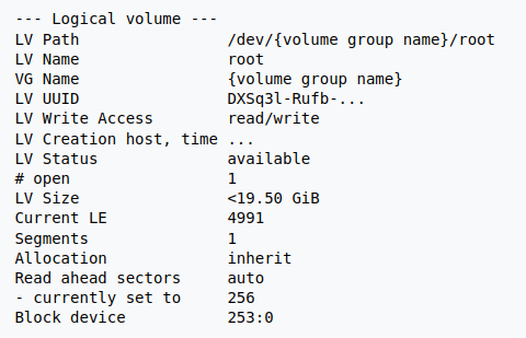
lvdisplay

note your LV Path: /dev/{volume group name}

parted /dev/sda
   print and fix
   quit
pvresize /dev/sda3
lvextend -l +100%FREE /dev/{volume group name}
resize2fs /dev/{volume group name}

Now use the next command to see if your LV path has increased with the free space available

df -h

Upgrading network application on UCK G2 with SSH

  • Connect to your cloudkey with SSH.
    Use root as username and the password set in the Unifi OS console
  • Download the version of the app you want to install:
    wget https://dl.ui.com/unifi/6.5.55/unifi_sysvinit_all.deb
    (You can find links on the release notes for the relevant version).
  • Run dpkg -i unifi_sysvinit_all.deb
  • Run rm unifi_sysvinit_all.deb

Proxmox Unprivileged Container Backup failed, Permission denied

When trying to take a full stop backup of my LXC containers in Proxmox, I get the following error output:

INFO: starting new backup job: vzdump 107 --mode stop --compress zstd --remove 0 --node hp2 --storage truenas-nfs-hdd --notes-template ''
INFO: Starting Backup of VM 107 (lxc)
INFO: Backup started at 2022-08-20 15:12:12
INFO: status = running
INFO: backup mode: stop
INFO: ionice priority: 7
INFO: CT Name: pihole-secondary
INFO: including mount point rootfs ('/') in backup
INFO: stopping virtual guest
INFO: creating vzdump archive '/mnt/proxmox-nfs-hdd/dump/vzdump-lxc-107-2022_08_20-15_12_12.tar.zst'
INFO: tar: /mnt/proxmox-nfs-hdd/dump/vzdump-lxc-107-2022_08_20-15_12_12.tmp: Cannot open: Permission denied
INFO: tar: Error is not recoverable: exiting now
INFO: restarting vm
INFO: guest is online again after 5 seconds
ERROR: Backup of VM 107 failed - command 'set -o pipefail && lxc-usernsexec -m u:0:100000:65536 -m g:0:100000:65536 -- tar cpf - --totals --one-file-system -p --sparse --numeric-owner --acls --xattrs '--xattrs-include=user.*' '--xattrs-include=security.capability' '--warning=no-file-ignored' '--warning=no-xattr-write' --one-file-system '--warning=no-file-ignored' '--directory=/mnt/proxmox-nfs-hdd/dump/vzdump-lxc-107-2022_08_20-15_12_12.tmp' ./etc/vzdump/pct.conf ./etc/vzdump/pct.fw '--directory=/mnt/vzsnap0' --no-anchored '--exclude=lost+found' --anchored '--exclude=./tmp/?*' '--exclude=./var/tmp/?*' '--exclude=./var/run/?*.pid' ./ | zstd --rsyncable '--threads=1' >/mnt/proxmox-nfs-hdd/dump/vzdump-lxc-107-2022_08_20-15_12_12.tar.dat' failed: exit code 2
INFO: Failed at 2022-08-20 15:12:17
INFO: Backup job finished with errors
TASK ERROR: job errors

Research

Some posts recommend setting a local temp directory in /etc/vzdump.conf for each node. While this would work, my nodes do not have a lot of local storage, and there is the potential for them to run out of space when taking backups. Additionally, I would rather not have the write cycles on the boot drives if possible.

There was another post that recommended verifying that the folders are actually writeable, and adjusting the permissions by running chmod 755 if they are not. There were no issues with the permissions set on my folders, so this is not my issue, but it may be worth checking.

The Solution

This post mentions mapping all users to root as part of the NFS configuration. Because LXC containers use linux namespaces, the user in an unprivileged container will not be root, and therefore you have to map all users. In the configuration of my NFS share on my Synology NAS, I altered the NFS-permissions squash to MAP ALL USERS TO ADMIN.


Rebooted my proxmox server and then the backup of unpriviliged LXC containers worked.

How to Backup Proxmox to a Synology NAS

1. Synology NAS Configuration

Before we configure Proxmox, we need to set up NFS permissions on our Synology NAS. This will allow Proxmox to read and write to our Synology NAS.

1.Open the Control Panel on Synology DSM and select File Services then NFS.

2. Select Enable NFS service and then Apply.

NOTE: You can leave the Maximum NFS protocol as NFSv3.

3. Select Shared Folder, then Edit the folder where you’d like your Proxmox data to be stored.

NOTE: If you aren’t sure how to create a Shared Folder, you can click this link to learn how.

4. Select NFS Permissions then Create.

5. In the NFS rule, add the IP Address of your Proxmox server. Leave the privilege as Read/Write and then select Allow users to access mounted subfolders.

6. Save everything and then log in to Proxmox.

2. Proxmox Configuration

Now that our Synology NAS has been configured, we will need to set up Proxmox to read/write from our Synology NAS. We’ll then be able to backup Proxmox to a Synology NAS.

  1. Select Datacenter then Storage.

2. Select Add then NFS.

3. At the NFS screen, create an ID, then enter the IP Address of your Synology NAS server. In the Export drop-down menu, the location of your Proxmox folder should automatically appear. In the Content drop-down, select ALL entries. You can then select Add.

4. Proxmox should now show the Synology NAS Storage that we created above.

3. Back up an Individual Virtual Machine

Now that we configured Proxmox and our Synology NAS, we can easily back up a virtual machine.

  1. Select the virtual machine you’d like to back up, then select Backup.

2. In the backup tab, select the Synology NAS storage location in the top right. This will ensure that we back up to the correct location.

3. Select Backup now in the top left corner.

4. Select your StorageMode and Compression, then select Backup and the backup will start!

3. Automatic Backups – How to Backup Proxmox to a Synology NAS

You can easily configure Automatic backups in Proxmox for all of your virtual machines if you’d like. This will automatically back up every virtual machine on a specific schedule.

  1. Select Datacenter then Backup, then select Add.

2. Select the Storage for your Synology NAS, then specify the ScheduleSelection modeCompression, and Mode.

3. You can also change the retention policy to only keep a certain number of versions by selecting the Retention tab. 
Without specifying a retention policy, all backups will be stored which will drastically reduce storage space on your Synology NAS over time.

4. Your virtual machines will now back up to your Synology NAS automatically after you select Create!

4. Restoring a Virtual Machine from a Backup

After the backups have been created, you can easily restore your virtual machine to one of them if you ever need to.

  1. Select the virtual machine, then Backup.

2. Select the Synology NAS storage in the top right under Storage.

3. Select the snapshot you’d like to restore to, then select Restore.

4. All information can stay as default, then select Restore.

5. You will receive a message that this will permanently erase the existing virtual machine. If you agree, select Yes. Your virtual machine will now be restored from the backup you selected!

5. Conclusion – How to Backup Proxmox to a Synology NAS

This tutorial shows how to backup Proxmox to a Synology NAS. Overall, this is a really good way to ensure that your virtual machines are backed up properly and automatically. This also gives you a pretty easy path to backing them up offsite using Hyper Backup if you’re interested.

Thanks so much for checking out the tutorial. If you have any questions on how to backup Proxmox to a Synology NAS, please leave them in the comment section of the YouTube video above!

Credits to Wundertech.net

Wireguard on Proxmox LXC container

Prerequisites before starting the tutorial
Download the Ubuntu 18.04 CT template onto a storage drive in Proxmox.

Then follow this youtube tutorial with the code listed below

First create your LXC container using the CT template you downloaded earlier

In PVE shell run following commands to finalize your setup

cd /etc/pve/lxc
nano (container number)

add these lines at the end
lxc.cgroup2.devices.allow: c 10:200 rwm
lxc.mount.entry: /dev/net dev/net none bind,create=dir

Save and close nano

run this command
chown 100000:100000 /dev/net/tun

check that it worked
ls -l /dev/net/tun
output should be something like this
crw-rw-rw- 1 100000 100000 10, 200 Dec 22 13:26 /dev/net/tun

To install Wireguard in your newly created container:

Open the console of the container and login as root with the password you made during the container creation
Then visit pivpn.io to get the install link and copy this in the terminal and execute it.
curl -L https://install.pivpn.io | bash

Just follow all steps during the installation wizard and you’ll have a working Wireguard instance at the end.

Setting up a WireGuard VPN server on the Raspberry Pi

Credits:
I Found this good tutorial for installing Wireguard on https://pimylifeup.com/raspberry-pi-wireguard/

In this section, we will do some initial preparatory work to make sure our Raspberry Pi is ready to install the WireGuard VPN software.

1. The first thing we need to do is ensure our Raspberry Pi is using the latest available packages.

We can do that by running the following two commands.

sudo apt update
sudo apt full-upgrade

2. We need to install the only package that we require to run the install scripts we need.

While this package should be available on most distributions of the Raspbian operating system, we will make sure by running the command below.

sudo apt install curl -y

Installing WireGuard on the Raspberry Pi

Within this section, we are going to make use of the PiVPN script to install WireGuard.

PiVPN makes the process of installing WireGuard on our Raspberry Pi a straightforward process. The script sets up the best defaults for our device.

Starting the PiVPN Install Script

1. Let us start the installation process by running the following command.

curl -L https://install.pivpn.io | bash

This command will use curl to download the PiVPN setup script from their website and then pipe it straight to bash.

You can verify this script’s contents by going directly to the install PiVPN domain in your web browser.

Installing WireGuard to your Raspberry Pi

1. The first screen you will be greeted with will let you know what this script is about to do.

To start the WireGuard installation process, press the ENTER key.

2. The first thing that we will be configuring through this script is a static IP address.

This screen explains why your Raspberry Pi should have a static IP address when operating as a WireGuard VPN server.

To proceed, press the ENTER key to proceed.

3. You will be asked if you are already using DHCP reservation.

Using DHCP reservation allows you to make your router assign an IP address to your Raspberry Pi.

In this guide, we are going to assume you haven’t used DHCP reservation and will move on to set a static IP address on  the Pi itself.

Select the <No> option and press the ENTER key to continue.

4. To set a static IP address for the WireGuard software. The installation script will want to use your default settings.

If the default IP address and gateway are correct to you, then you can safely select the <Yes> option.

Continue with this WireGuard set up guide by pressing the ENTER key.

5. You will be warned that you can potentially run into IP conflicts when using this method.

The way around that is to use DHCP reservation. However, most routers should be smart enough to stop this from being a problem.

Press the ENTER key to continue.

6. This screen will tell you that you need to specify a local user to store the WireGuard configuration files.

Continue to the next screen by pressing the ENTER key.

7. You can now select from a list of available users.

Use the ARROW keys to highlight the user then the SPACEBAR to select it.

Once you are happy with the user you have selected, press the ENTER key.

8. Finally, we can select the VPN software we want to install.

As we want to install WireGuard to our Raspberry Pi, you can press the ENTER key to continue.

The reason for this is that default by the PiVPN script selects WireGuard.

9. This screen will allow you to change the port the WireGuard uses on your Raspberry Pi.

It is recommended to keep this the same unless you have a particular reason to change the port.

Press the ENTER key to confirm the specified port.

10. This screen just confirms the port that you set your Raspberry Pi WireGuard VPN to use.

Please note to be able to access your WireGuard VPN from outside of your home network, you will need to port forward the port mentioned here. The type of this port is UDP.

Confirm that the port is still correct, then press the ENTER key to proceed.

11. We can now specify the DNS provider that we want to use for our VPN clients.

For our tutorial, we chose to use the Cloudflare one as it is relatively speedy, and they purge their logs every 24 hours.

Use the ARROW keys to navigate through this menu. Once you have found the DNS provider you want to use, press the SPACEBAR key.

If you are happy with your selection, press the ENTER key to confirm it.

12. You can specify two different ways you want to access your WireGuard VPN.

Using your public IP address is the easiest option. However, this should only be used if you have a static IP address.

The other option is to use a domain name. You can set up this option by following our dynamic DNS guide.

For this guide, we will be sticking with using our public IP address.

Once you have the option you want to be selected, press the ENTER key to proceed.

13. The PiVPN script will now generate the server key that WireGuard requires.

All you need to do here is press the ENTER key again.

14. This screen will give you a quick rundown about unattended-upgrades and why you should enable them.

Go to the next step by pressing the ENTER key.

15. You can now enable the unattended-upgrades by selecting the <Yes> option.

We highly recommend that you enable these to ensure your Raspberry Pi will download security fixes regulary.

Not enabling this will potentially leave your WireGuard VPN vulnerable to attack.

Once you have the option you want to be selected, press the ENTER key to confirm it.

16. You have now successfully installed the WireGuard VPN software to your Raspberry Pi.

This screen will let you know that you still need to create profiles for the users, which we will cover in the next section.

Press the ENTER key to continue to the last two steps.

17. You will be asked whether you want to restart your Raspberry Pi before continuing.

We recommend that you choose the <Yes> option.

Once you have selected to reboot, press the ENTER key twice to restart.

Creating your First WireGuard Profile on your Raspberry Pi

Now that we have successfully installed the WireGuard software to our Raspberry Pi, we can create a profile for it.

To be able to create this profile, we will be making use of the PiVPN script again.

1. To begin creating a new profile for WireGuard, we need to run the following command.

sudo pivpn add

2. All you need to do is type in a name for the profile that you are creating.

For example, we will be calling our profile “PiMyLifeUp“.

Once you have created a profile, it will be stored within the directory specified in the output.

If you followed the previous steps and used the pi user, you will be able to find the config file within the /home/pi/configs directory.

As a final step edit the PiMyLifeUp in /home/pi/configs to include the listenport in the interface section, otherwise you will look like connected to the server, but no data is send.

[Interface]
PrivateKey = xxxxxxxxxxxxxxxxxx
Address = xx.xx.xx.xx/24
DNS = 9.9.9.9, 149.112.112.112
ListenPort = 51820

You can use the config file within here to set up your WireGuard clients. However, there is another method which we will go into in the next section.

Generating a QR Code for your WireGuard Profile

In this section, we will show you how to generate a QR code for the WireGuard profile we generated on our Raspberry Pi.

You will be able to scan this QR code using your device. This saves you from having to copy the config file from your device.

Luckily for us, the PiVPN software comes with a QR code generator that we can use.

1. To generate a QR code for your profile, you will need to start by running the following command.

Make sure you replace “PROFILENAME” with the name you set in the previous section. In our case, this will be “PiMyLifeUp“.

pivpn -qr PROFILENAME
or
pivpn -qr

And select the profile you are generating the QR code for

2. You can then scan this QR code using your iOS or Android devices.

You can find the WireGuard app on both the Google Play Store and the Apple App Store.

When scanning the QR code, you will be asked to enter a name for the profile.

At this point, you should now have successfully got a WireGuard VPN running on the Raspberry Pi.

Finally, when you have done all steps and are able to connect to the WireGuard server on your Pi, but unable to connect to your LAN or the internet, then run the following command and make the necessary repairs to get it fixed

pivpn -d

If you need to show the QR code for a profile afterwards, then use the following command

sudo su
qrencode -t ansiutf8 < /etc/wireguard/clients/PROFILE.conf

When you have imported the profile in your mobile app and did not change the profile.conf file manually, then change the listen port for the server in the wireguard app from automatic to 51820 or the port you used when installing the wireguard server.

You can use the following code to check the connection status of your clients

sudo wg show

This will be the displayed result

interface: wg0
public key: xxxxxxxxxxxxxxx=
private key: (hidden)
listening port: 51820

peer: xxxxxxxxxxxxxxxx=
preshared key: (hidden)
endpoint: xx.xx.xx.xx:xx
allowed ips: xx.xx.xx.xx/32
latest handshake: 24 minutes, 30 seconds ago
transfer: 99.52 KiB received, 314.70 KiB sent
Setting up a secure IoT network using UniFi

This tutorial goes over how to set up a secure internet of things (IoT) network in UniFi with Google Cast and Airplay across VLANs.

Objectives

  • IoT network segregated from main LAN
  • Allow routing between IoT network and main LAN for AirPlay and Google Cast, but no other traffic should be routed
  • Create a VLAN in the UniFi SDN which allows us to assign access ports to the IoT network for wired devices


1. Setup IoT LAN

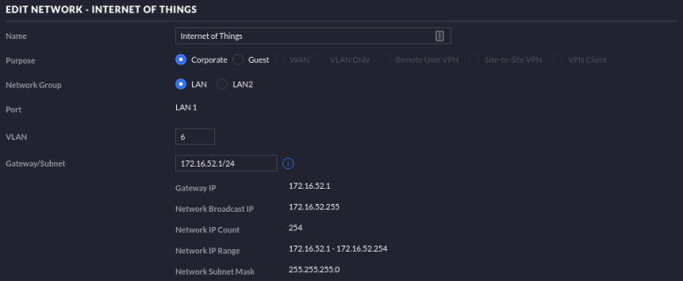
First, we have to setup our network for the IoT devices. To do this, navigate to Settings > Networks > Create New Network in UniFi.

The network should be marked as Corportate and have a unique (unused) VLAN assigned to it. Follow your standard IP addressing scheme and assign a subnet. For home deployments, a /24 should have more than enough IP addresses for your devices.


2. Make the IoT WiFi Network

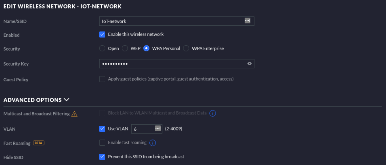
The majority of your Internet of Things devices will probably be connected using WiFi, so we have create a wireless network next. Navigate to Settings > Wireless Networks > Create Wireless Network in UniFi.

Next, expand the Advanced Options and tag this network with the same VLAN that we created earlier. In this case, it will be VLAN 6. You should also check the box near “Prevent this SSID from being broadcast” since this network doesn’t need to be publicly visible.


3. Secure the IoT Network – Routing & Firewall Rules

By now, you will have both an IoT VLAN and an IoT WiFi network. However, these are in no way segregated from your main LAN, and aren’t secure. Now, we will secure our IoT network.

3a. Allow Established/Related connections

The first rule we are adding is to allow established and related connections. If you aren’t sure what those are, you might want to check out this Wikipedia page.

To add this rule, go to Settings > Routing & Firewall > Firewall > Rules IPv4 > LAN In > Create New Rule in UniFi. Call it “Allow Established/related sessions” and make sure that it is run before the predefined rules. Make sure to select the Action as “Accept”. On the same page, under Advanced > States, check “Established” and “Related”. For “Source”, you want to select the “Network” option and select your Internet of Things VLAN in the dropdown. For “Destination”, again, select “Network”, and select your main LAN in the dropdown.

3b. Drop IoT to Main LAN

If you were to login to the IoT WiFi network right now and ping a device on your main LAN right now, it would respond. Now, we have to instruct the USG to disallow routing all traffic that does not match the rule we have just defined in the previous step.

Staying in the LAN In section, create another new rule. Name it “Drop IoT to Main”, and have it run After Predefined Rules. Ensure the action matches “Drop”, and select the Source to be from network “Internet of Things”, and the destination to be from network “LAN”.

4. Enable mDNS Reflector for Google Cast and AirPlay

Casting protocols like Google Cast and AirPlay use an IP routing concept called multicast to discover devices on the network and advertise themselves as players. Right now, our network would work as a walled-off network, but we would not be able to use Google Cast without switching our own device to the IoT network, which is not ideal and defeats the purpose.

Go to Settings > Services > mDNS and enable it, and Apply your settings changes.

Conclusion

You should now have a functioning and secure IoT network. If you connect to the IoT network, you shouldn’t be able to ping a device on the main LAN or reach it on the local area network. However, if you have something like a Google Home and you are on the main LAN, you should be able to cast to it despite it being on the secured IoT network.

Add Smartwares CIP-37210AT IP camera in Surveillance Station

I managed to add the Smartwares CIP-37210ET IP camera, which I got from the Action store, in Synology Surveillance Station. I will explain how I did it below.

First install your camera with the HomeWizard Cameras app from smartwares.eu.
Write down the camera password you created at the end of the wizard.

Next thing to do is assign a fixed IP address to the camera. The software of the camera doesn’t support that, so you need to do that in your internet router.

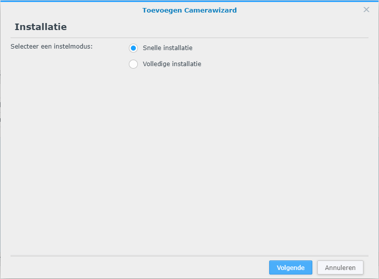
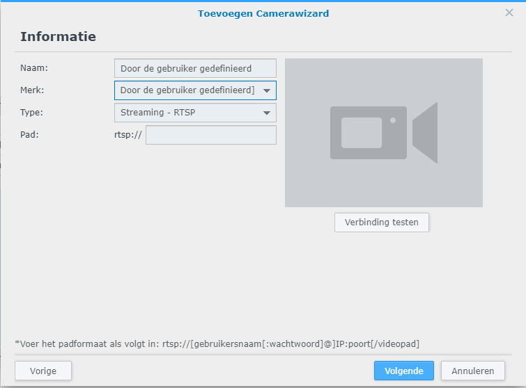
Once you have done that, open Surveillance Station and add a camera and choose quick installation

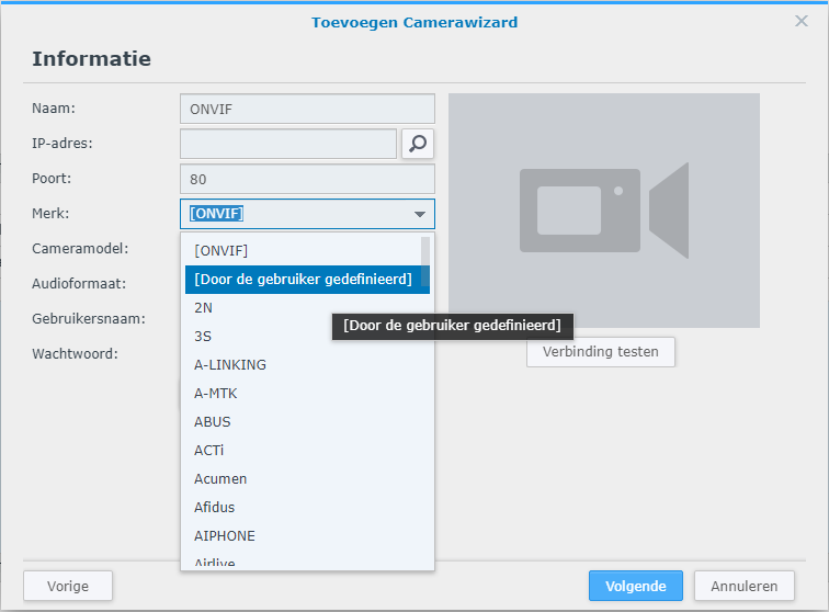
Then choose in the brand selection screen the option defined by user

In the path you need to enter the url for the stream using the camera password you created during the wizard in the app on your phone

rtsp://admin:PASSWORD@IP:554/live/av0?

PASSWORD: password you created
IP: the fixed IP you assigned to your camera

The link you have to enter is the above text except for the rtsp://

admin:abcde12345@192.168.0.240:554/live/av0?

Now you can test the connection and if everything is done right, you should see the video stream.

Synology Surveillance Station Home Mode Automation with Home Assistant

I have found a guide on the www, but it was not that 100% clear and I had to google a lot of things to be clear. But I got it 100% functional and will publish an updated guide here.

This is the url for the original guide: https://www.paolotagliaferri.com/home-automation-home-assistant-docker-synology/

Some prerequisites:

  • Docker
  • Home Assistant
  • Surveillance Station
  • Unifi network or similar that can be integrated in Home assistant

First:

Find the entity identifier of your mobile phone that is used by the Ubiquiti UniFi integration

Create a group where the entity that represents you in your configuration.yaml

Next:

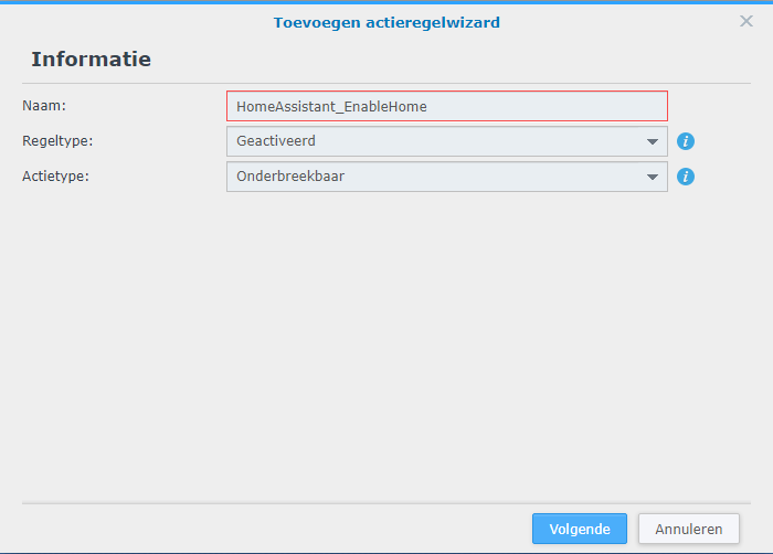
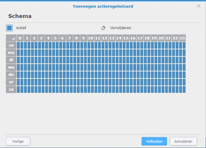
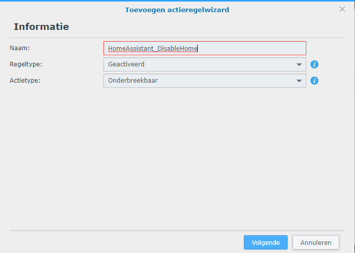
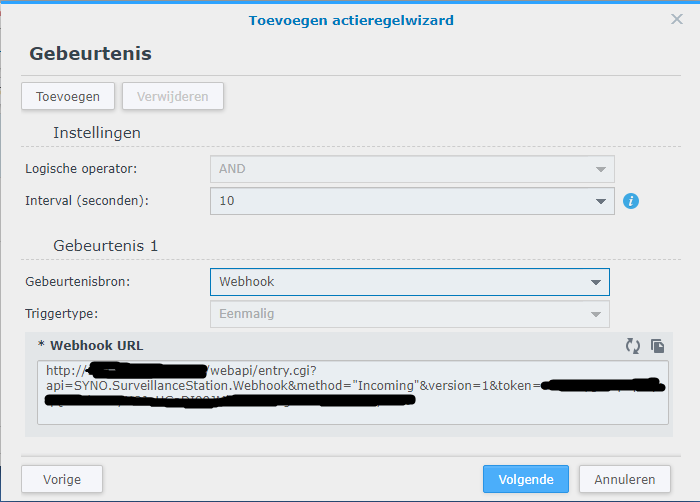
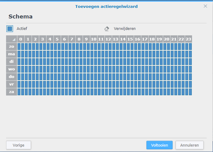
Then on the Synology Surveillance Station, I generated two actions in the Action Rule section to create webhooks that Home Assistant can use for switching the Home mode on or off

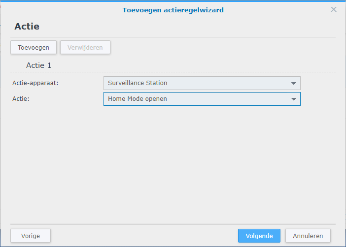
First I will create the rule to enable home mode

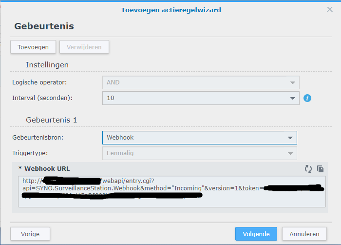
Here you see the webhook url we will use in the secrets.yaml later on

Now you have create the rule to enable the Home mode in surveillance station. Next will be the disable Home mode rule

Here you see the webhook url we will use in the secrets.yaml later on

When you have followed all steps, this will be the result

Now we are going to define 2 variables for the webhooks in the secrets.yaml file. These variables will be used in the configuration.yaml later.

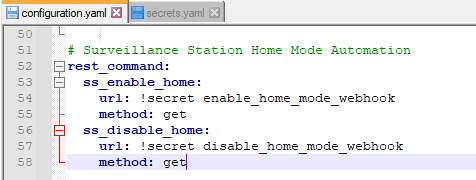
When that is done, we can go back to the configurations.yaml to define the webhooks so they can be used for automation

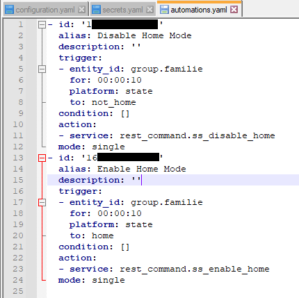
Finally – I defined the automation in the UI (or in the configurations.yaml file) – here’s the generated configuration

Last thing to do is to check the configuration for errors and if that passes, you can restart the Home Assistant server.

Now the moment you go out of range of your wifi, Synology Surveillance station will go out of home mode and vica versa. Keep in mind that the standard delay the Ubiquiti UniFi integration uses for switching from home to not home is 300 seconds.